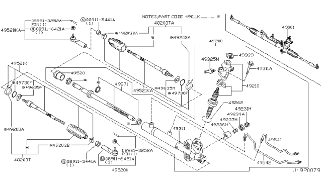
On 2007 and later 635 Sedans, the front subframe must be lowered for clearance to remove the rack and pinion, requiring a suitable floor jack. Additionally, on models with four-wheel active steering or steering angle sensors, sensors must be calibrated before and after the procedure at a dealership service department. For removal: Park the vehicle with the wheels pointing straight ahead, loosen the front wheel lug nuts, raise the front, support on jackstands, apply the parking brake, and remove the wheels. Remove the lower engine splash shield. Detach the tie-rod ends from the steering knuckles. Mark the relationship of the intermediate shaft coupler to the rack and pinion input shaft, remove the pinch bolt, and separate the coupler from the input shaft. For 2007 and later G35 Sedans, it's recommended to use new mounting fasteners for the subframe. On 2WD models, remove the brace under the rear portion of the subframe. For AWD models, remove the suspension reinforcement brace installed on the front of the suspension, which is recognized by a series of tubes and plates formed into a single unit held by eight bolts. Remove the ABS wheel speed sensors from the steering knuckles. On AWD models, remove the shock absorbers. Remove the lower control arm. For 2WD models, remove the stabilizer bar. Install an engine support fixture on the engine top or use an engine hoist for the engine and transaxle. Detach the rack and pinion line and hose bracket from the subframe and the engine mounts from the subframe. Support the rear of the subframe with a floor jack and remove the two rear subframe mounting bolts. Carefully lower the subframe for access to the rack and pinion mounting fasteners, ensuring the rack and pinion input shaft and intermediate shaft coupler separate without binding. Check for any wiring harnesses or hoses that may tension as the subframe is lowered and detach if necessary. On models with four-wheel active steering, disconnect any electrical connectors attached to the rack and pinion. Position a drain pan under the rack and pinion, disconnect the power steering pressure line, and detach the return hose, capping all openings to prevent fluid loss. Remove the mounting fasteners and the rack and pinion. Inspect all rubber bushings for wear and replace if damaged.For installation: The process is the reverse of removal, ensuring the following: Tighten rack and pinion mounting bolts and the lower intermediate shaft coupler pinch bolt to torque values. Carefully raise the subframe, guiding the Rack And Pinion input shaft into the intermediate shaft coupler. Install and tighten the rear subframe mounting bolts. Reattach any removed wire harnesses or brackets. Fill the power steering pump with recommended fluid, bleed the system, and recheck fluid levels. Run the engine, check for operation and leaks, then shut off and recheck fluid levels. Install the wheel and lug nuts, lower the vehicle, and tighten the lug nuts. Have the front-end alignment checked and adjusted if necessary. On models with active steering or sensors, calibrate the system at a dealership.
Posted by InfinitiPartsDeal Specialist 


